|
|
 |
|||||||||
|
Multi-Spectral Imagery LRC Project EH3841Magnetometry: The Instruments Using a single magnetic detector of any type is prone to a number of problems associated with two separate but related areas; the attitude of the detector in relation to the ground surface and the prevailing magnetic field, and the diurnal variation in the Earth’s geomagnetic field. As the planet rotates, the magnetic field falls in the morning and rises at the end of the day, by 5 nT in winter, but by as much as 50 nT during summer (Clark, 1996, 67). In order to avoid the problems of diurnal fluctuation, differential magnetometers were devised. This involved the collection of data from two different but identical sensors at the same time; one sensor moving across the survey area, and another taking readings at a fixed location. This allowed any fluctuation in the ambient magnetic field to be adjusted for. Gradiometers are a variant on this design, with both detectors housed in a single tube. They operate by subtracting the readings of the upper, or reference sensor (measuring the Earth’s magnetic field) from the lower sensor (measuring the Earth’s magnetic field as well as the effect of any localised magnetic anomaly) to obtain a reading which indicates localised magnetic strength. In effect, this means that if there is no magnetic anomaly in the vicinity, then the reading obtained will be zero, although in practice this is rare, as both soil “noise” and instrument calibration stability (or drift) will also have an effect on the readings. A factor to consider is that in a gradiometer array the sensors are usually so close together that both of them will be affected by a strong localised anomaly. However, in practice this does not detrimentally affect the ability of modern gradiometer arrays to detect both weaker and stronger anomalies. Fluxgates are electronic magnetic detectors, and are extremely directionally sensitive, so that they are almost always used in a gradiometer array, where the two sensors are spaced at a regular interval (usually 0.5 or 1 metre apart) in a rigid tube. Recently, there has been much debate on whether “total field” sensors (i.e. those used in caesium magnetometers) require calibration in this way, and research carried out by Becker (2001, 20-25) andTabbagh (2003, 75-81) indicate that data acquired by modern stable caesium arrays can be used without the use of a differential or gradiometer setup, although more data processing may be subsequently required to remove the effects of instrument drift and diurnal variation. A total field system does not initially require that a zero reference point is found, as it measures the absolute strength of the magnetic field in nT, including that provided by the Earth. However, initial calibration and checks on the Earth’s magnetic field periodic drift are required. The instruments used by the LRC from 1990 to 2007 are the Geoscan Research FM36 fluxgate gradiometer and the Bartington Grad 601-2 fluxgate gradiometer.
The Geoscan Research FM36 fluxgate gradiometer The instrument is a light, rigid aluminium tube 50 centimetres long, with a fluxgate sensor mounted at either end. A data logger, the power supply and the controls are also mounted on the carrying handle to make the instrument fully portable. In use, the two sensors are aligned, balanced, and zeroed manually and the instrument is then carried vertically alongside the operator's body. The measurements taken are stored in the data logger, and periodically transferred to a portable computer in the field. With the FM36, this needed to be done every four 30m grids, and takes 20 minutes to download.
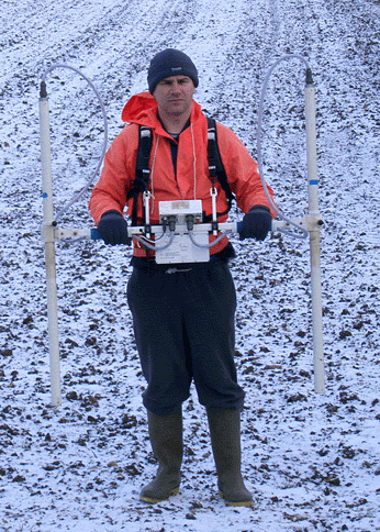
The model has been superseded by the FM256, which has a greater memory capacity and a faster download speed. It also has the capability of being linked with another FM256 or FM36 in a dual array, allowing faster survey times to be achieved. For further details, the Geoscan Research webpage dealing with the new model is: http://www.geoscan-research.co.uk/page28.html. The Bartington Grad 601-2 fluxgate gradiometerThe Bartington Grad 601-2 is a lightweight construction, with a crossbar containing the memory, controls and power supply, supporting 2 one metre long tubes, with each tube containing a fluxgate at either end. This dual sensor mode has the advantage of cutting surveying time almost in half, compared to the use of a single sensor. In use, the Grad 601-2 is carried to a zero reference point and then zeroed, this being an automatic rather than a manual process as with the FM36.
As can be seen from the image above, fluxgate gradiometers are not unduly affected by adverse weather conditions, even if the operators are! For further details, theBartington webpage dealing with the instrument is: http://www.bartington.co.uk/index.php?id=70
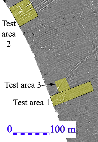
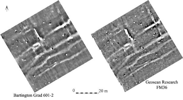
Comparing the two instrumentsIn January 2003, Geoff Bartington of Bartington Instruments kindly lent us one of his dual sensor Grad 601-2 fluxgate gradiometers, which allowed us to test the returns from this instrument against those from the Geoscan Research FM36 gradiometer. We carried out two comparison tests, with test area 1 located over a round barrow and its environs and test area 2 over part of a late Iron Age/Romano-British ladder settlement, both of which were located in site 073. Both machines were set to detect magnetic variations of 0.1nT, and the zigzag traverse method was used for all surveys. In addition, a single grid (test area 3) was traversed in a number of different orientations, to establish how much of an effect the direction of the traverse had when crossing a linear feature.
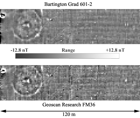
Test area 1 (see image below) was a line of four 30m grids, here shown ungeoreferenced, with the first grid over a multiple ditch round barrow. The FM36 data was collected on the 31/12/2002, and Grad 601-2 data on the 06/01/2003. Generally, the returns from both instruments was similar, in that there was nothing in one set of data which could not be seen in the other. The Grad 601-2 data has a slightly smoother look to it, and some of the dipoles caused by iron spikes were either muted or not present. This may be due to a slightly different sensor height (the FM36 was carried slightly closer to the ground), or it could have been caused by different in-machine processing of the data. The Grad 601-2 manual (http://www.bartington.com/pdfs/opmanuals/om1800.pdf available online from website http://www.bartington.com/operations.htm) states that “Integrating the readings over the measurement interval reduces the noise level, but also effectively limits the bandwidth.”.
Test area 2 (see below) was a 60m square, consisting of four 30m grids. The Grad 601-2 data was collected on the 06/01/2003, and the FM36 data on the 15/01/2003. Once again, the two machines give a similar return, although the eastern two grids of the Grad 601-2 seems to have slightly less definition than the FM36 data. This was before we realised quite what an effect the height of the sensors above the ground had on the data, and these grids were walked by a very tall person!
The conclusions we reached were that both instruments were giving a very similar response, although the 1m separation of the Bartington sensors may have contributed to the "smoother" look to the survey data. The archaeological features in this area are not deeply buried, so we could not test the claim that the 1m sensor separation would allow deeper features to be identified.
|
|||||||||
